
Funkwerk (bintec) router installation guide
The routers described in this article are referred to as "Funkwerk", or "bintec" routers. Funkwerk AG acquired bintec Access Networks in 2003. The article will generally refer to the router as a bintec product.
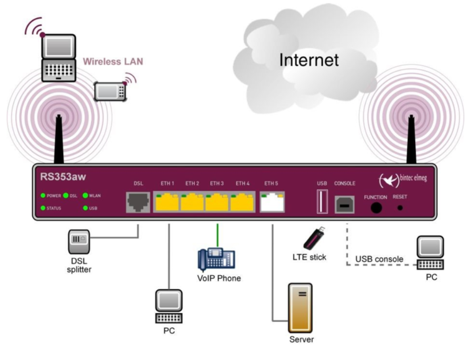
The bintec gateway routers enable an individual workstation or small company network to connect to the Internet and other partner networks (for example, to a corporate network).
This article describes the hardware installation procedure for the bintec RS123, RS123w, RS353a, and RS353aw router models. At the end is an Additional information section providing supplementary information that may be of use to the reader.
Once the installation is complete it is then necessary to carry out the software configuration required to enable network access. The following Cloud Direct knowledge articles are available to assist later with router configuration.
- KB0010930, Configuring a router for ADSL
- KB0010931, Configuring a router for EFM
- KB0010932, Configuring a router for FTTC
In addition to the content in this article, the bintec website is a useful source of information, including:
- The bintec RS Series user manual, https://www.bintec-elmeg.com/fileadmin/user_upload/Downloads/29/RS-NG_Series_Manual_en.pdf,
- The bintec product FAQs, http://classic.faq.bintec-elmeg.com/faq_bintec_vpn_ipsec_kategory_en,76408,1361.html.
Prerequisites
Before commencing this procedure, the following are required.
- Mains voltage supply – AC voltage of 100 to 240 V, 50 to 60 Hz.
- Your router package, including cables and connectors.
Caution:
Please read the safety notices supplied with the device before installing and starting up your router.
Your router package
Depending on the model you have ordered, your router package will contain the following items in addition to the actual router.
|
Parts |
RS123 |
RS123w |
RS353a |
RS353aw |
|
Cable sets/mains unit/ other |
Ethernet cable (yellow) ISDN cable (black) Power cable 19" Mounting frame, and screws |
As RS123, plus: 2 external WLAN antennae |
As RS123, plus: xDSL cable type 2 (grey) |
As RS123, plus: xDSL cable type 2 (grey), |
|
Software |
Companion DVD, Dime Manager (on DVD) |
|||
|
Documentation |
Quick Install Guide and safety notices (printed). |
|||
Installation options
Your router may be installed as a table top unit, within a 19 inch cabinet, or wall mounted.
- As a table-top device - Attach the four self-adhesive feet to the bottom of the device, then place your device on a solid, level base.
- In a 19 inch cabinet - Screw your device into the cabinet using the supplied brackets and screws.
- Wall mounted - Attach your router to a wall, use the tabs on the back side of the housing.
Note:
The devices offer the possibility of a Kensington lock to secure. You will find the required notch on the right side of the housing.
Front and rear panel connectors
The majority of connectors are located on the router front panel, but there are a few on the rear panel. The following paragraphs show the connectors on both front and rear panels.
Front panel connectors
Your router provides the following front panel connectors.
|
Connector |
Description |
RS123 |
RS123w |
RS353a |
RS353aw |
|
ETH1 / ETH2 / ETH3 / ETH4 (yellow) |
10/100/1000 Base-T Ethernet interfaces. Can be independently configured for use in a LAN, WAN, or DMZ subnetwork. |
Yes |
|||
|
ETH5 (white) |
10/100/1000 Base-T Ethernet interfaces |
Yes |
|||
|
USB |
USB connection type A |
Yes |
|||
|
USB CONSOLE |
USB console type B |
Yes |
|||
|
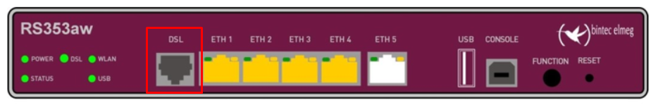
DSL (grey) |
VDSL interface for connectivity, via telephone line, to the internet. |
No |
Yes |
||
|
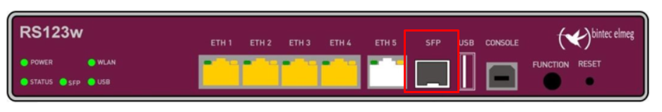
SFP |
SFP slot for 1000 Mbit/s Ethernet SFP fibre optic expansion (Port ETH5 is deactivated if a SFP module is equipped). |
Yes |
No |
||
Connector locations are illustrated below for the RS123w and RS353aw model routers.
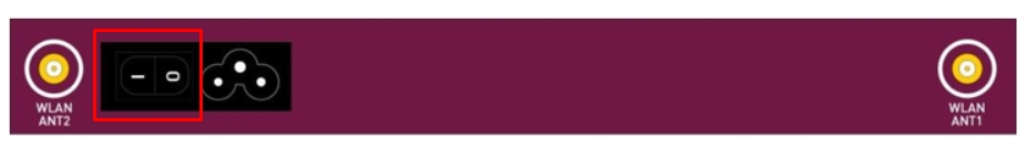
Rear panel connectors
The mains connector and the On/Off switch are located on the back of your router.
In addition, the bintec RS123w and bintec RS353aw models have connectors for two external Wi-Fi antennae, as shown below.

Connecting your router
To connect your router, refer to the illustrations in Front and rear panel connections and carry out the steps below in the order given.
- Connect the antennae (bintec 123w and bintec RS353aw only):
- Screw the two external WLAN antennae supplied, to the WLAN ANT1 and WLAN ANT2 connections on the rear panel of the router.
- Connect the ETH1-4 ports:
Caution:
Incorrect cabling of the ETH interfaces may damage your router. Connect the ETH interface of the router only to the LAN interface of the computer/hub, or a WAN interface if available.
- Connect the first switch port (ETH1, yellow connector) on your router through the supplied Ethernet cable to your LAN. The router automatically detects whether it is connected to a switch or directly to a PC.
- Connect more devices, or LANs, or WANs, to Ports ETH2 to ETH4.
- Connect the DSL ports (bintec RS353a and bintec RS353aw only):
Caution:
Incorrect cabling of the DSL interface may damage your device. Connect the DSL interface of the router only to the DSL connection.
- Connect the DSL interface (DSL, grey connector) of your device to the DSL output of the splitter, using the DSL cable (grey cable) supplied.
- Connect the power:
Caution:
The use of the wrong mains equipment may damage your device. You should use only the power supply unit provided!
- Connect the power socket, located on the rear panel, via the supplied power cord to your power supply.
- Set up further optional connections as required:
- ETH5 - Connect the ETH5 interface (white connector) of your device via an RJ45 cable to your LAN/WAN interface.
- USB - Connect a wireless flash drive to the USB port on your device.
- USB CONSOLE - For alternative configurations, connect the USB CONSOLE from your router via a USB cable to a PC. A suitable cable is available as an accessory.
The device is now ready for configuration with the GUI.
Please refer to one of the following knowledge articles for details of how to configure your router for operation.
- KB0010930, Configuring a router for ADSL
- KB0010931, Configuring a router for EFM
- KB0010932, Configuring a router for FTTC
Additional information
The following information is provided in addition to the installation procedure, and may prove useful to the reader.
Front panel LED indications
The front panel LED indicators provide information about specific activities and states of the router. The following table lists the LED indicators available on each router model.
|
Model |
Power |
Status |
USB |
ETH |
WLAN |
DSL |
SFP |
|
RS123 |
1 |
1 |
1 |
10 |
- |
- |
1 |
|
RS123w |
1 |
1 |
1 |
10 |
1 |
- |
1 |
|
RS353a |
1 |
1 |
1 |
10 |
- |
1 |
- |
|
RS353aw |
1 |
1 |
1 |
10 |
1 |
1 |
- |
The following table describes the status of each LED indicator.
|
LED |
Colour |
Status |
Description |
|
Power |
green |
on |
Power supply is connected. |
|
|
off |
No power supply. |
|
|
Status |
green |
on |
After switching on: The device has started. |
|
green |
flashing |
The device is active. |
|
|
green |
off |
During operation: An error has occurred. |
|
|
DSL |
green |
on |
VDSL connection established. |
|
green |
flashing |
Data traffic via VDSL send / receive. |
|
|
|
off |
No VDSL connection. |
|
|
SFP |
green |
on |
SFP connection is active. |
|
|
off |
No connection. |
|
|
|
flashing |
Data traffic via SFP interface. |
|
|
WLAN |
green |
on |
WLAN connection established. |
|
green |
off |
Radio or all assigned VSS inactive. |
|
|
green |
on (slowly flashing) |
VSS is active, no client connected. |
|
|
green |
on (fast flashing) |
VSS is active, at least one client connected. |
|
|
USB |
green |
on (flickering) |
VSS is active, at least one client connected, active data traffic. |
|
green |
flashing |
Data traffic via USB send / receive. |
|
|
|
off |
No USB connection. |
|
|
ETH 1 to 4: Link |
green |
on |
Ethernet connection established. |
|
green |
flashing |
Data traffic via Ethernet. |
|
|
|
off |
No Ethernet connection. |
|
|
ETH 1 to 4: Speed |
green |
on |
1000 Mbits transfer rate. |
|
orange |
on |
100 Mbits transfer rate. |
|
|
|
off |
10 Mbits transfer rate. |
|
|
ETH 5: Link |
green |
on |
WAN-Ethernet connection established. |
|
green |
flashing |
Data via ETH 5 send / receive. |
|
|
|
off |
No Ethernet connection. |
|
|
ETH 5: Speed |
green |
on |
The device is connected to the WAN at 1000 Mbits. |
|
orange |
on |
The device is connected to the WAN at 100 Mbits. |
|
|
|
off |
The device is connected to the WAN at 10 Mbits, or no Data transfer. |
Status LED during BRRP operation
BRRP (bintec Router Redundancy Protocol) is a bintec-specific implementation of VRRP (Virtual Router Redundancy Protocol). A router redundancy procedure is used mainly to protect the data of a service of a physical gateway in a LAN or WAN connected over Ethernet. You can determine the status of your router in BRRP operation (operating as Master router, or Backup router) with the aid of the Status LED.
|
LED |
Colour |
Status |
Description |
|
Status |
green |
flashing |
The device is functioning as a Master router. |
|
green |
Heartbeat (on-on-off) |
The device is functioning as a Backup router. |
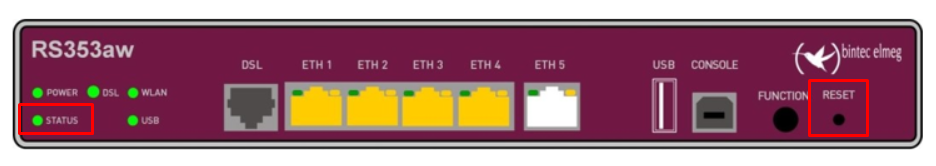
Reset
If the configuration is incorrect, or if your router cannot be accessed, then you can reset the device to the factory standard settings using the Reset button on the front panel.
Caution:
All existing data will be deleted if you reset the router.
To reset the device, proceed as follows.
- Switch off the router, using the On/Off switch on the rear panel.
- On the front panel, press the Reset button, and keep it pressed down until Step 4.
- Switch on the router using the On/Off switch on the rear panel.
The front panel Status LED will start to flash.
- Wait for the Status LED to flash five times, then release the Reset button.
Your device is now reset to factory settings, and may be reconfigured as required.
Note:
Deleting the boot configuration - If you delete the boot configuration via the GUI (menu Maintenance >Software & Configuration) then all passwords are also reset and the current boot configuration is deleted. When power is next applied to the router, it will boot with the standard factory settings.
